QCEngine quickstart
Installation
Assuming you’re reading this documentation through a web-browser, no installation is required to use QCEngine. Simply visit the QCEngine website to immediately start using its JavaScript interface.
The QCengine UI
Before detailing how to start writing QPU programs, we describe the different UI elements on the QCEngine webpage. These allow you to control simulations and a number of associated visualizations. When using the QCEngine UI, three windows are displayed:
The code window
This is used to enter and run code. JavaScript entered in the text-box will be syntax-highlighted. The window can be resized using the handle on the bottom right. Code entered into this window describes a simulation to be run with QCEngine. Typically this code will setup and initialize a group of qubits, perform some operations on them, and then read the out. The simulation specified by the code is only actually run (using the CPU of your local machine) after the Run Program button is clicked (see below).
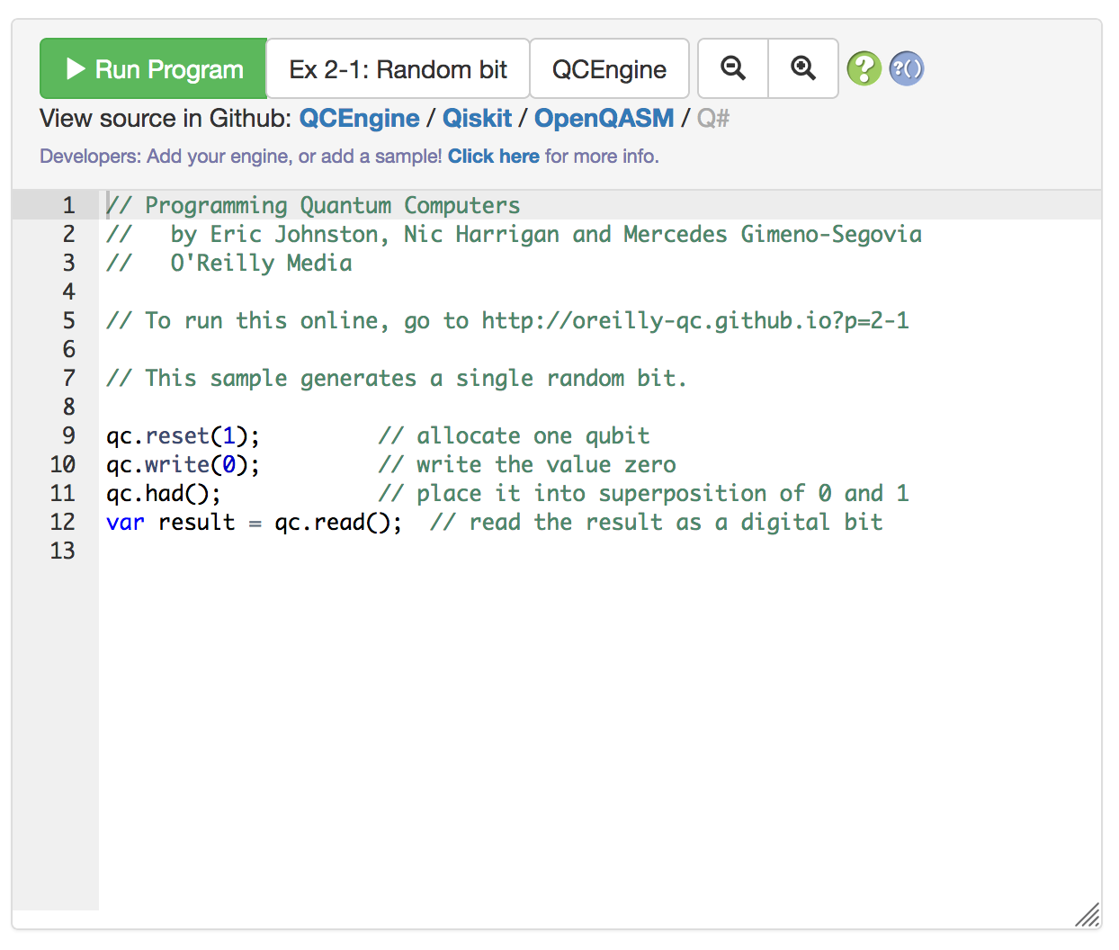
The Run Program button executes the code currently in the code window and consequently generates visualizations in the other UI windows described shortly.
The Examples dropdown menu (set to Ex 2-1: Random qubit in the above image) can be used to populate the code window with existing code samples from book, referred to by their Example number.
The Engine dropdown menu (set to QCEngine in the above image) can be used to change the simulator engine language for code displayed for the pre-existing book code-samples. Many code samples are also provided in the Qiskit and OpenQASM languages.
The magnifier buttons can be used to alter the text-size of code in the code window.
The circuit window
After the Run Program button has been clicked in the code window, the circuit window will display a circuit diagram for the code (assuming that the code is free from syntax errors).
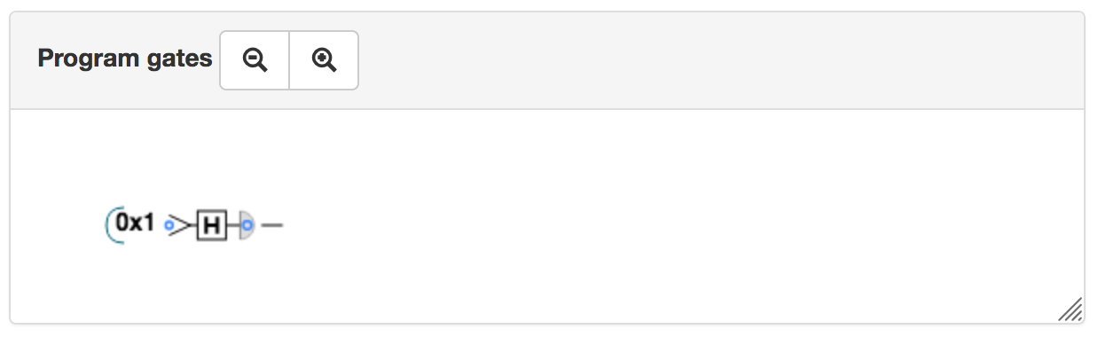
The magnifier buttons can be used to resize the circuit diagram within the circuit window. Using ctrl-scroll (holding ctrl whilst using a mouse/trackpad scroll gesture) also zooms in/out of the circuit diagram.
The circuit window interacts closely with the circle notation window (see below). When the cursor is hovered over a circuit diagram, a vertical orange bar appears to show which point in the circuit is currently being visualized in the circle notation window (defaults to the end of the circuit). Clicking on another part of the circuit will refresh the circle notation window to show a visualization of the QPU’s state at this new point in the circuit (and the vertical orange marker line in the circuit will move accordingly). This interface can be used to ‘step through’ a QPU circuit.
The circle notation window
This shows a visualization of the state of the QPU at a given point within the code. How to interpret circle notation visualizations is explained in detail in Chapter 2 of Programming Quantum Computers.
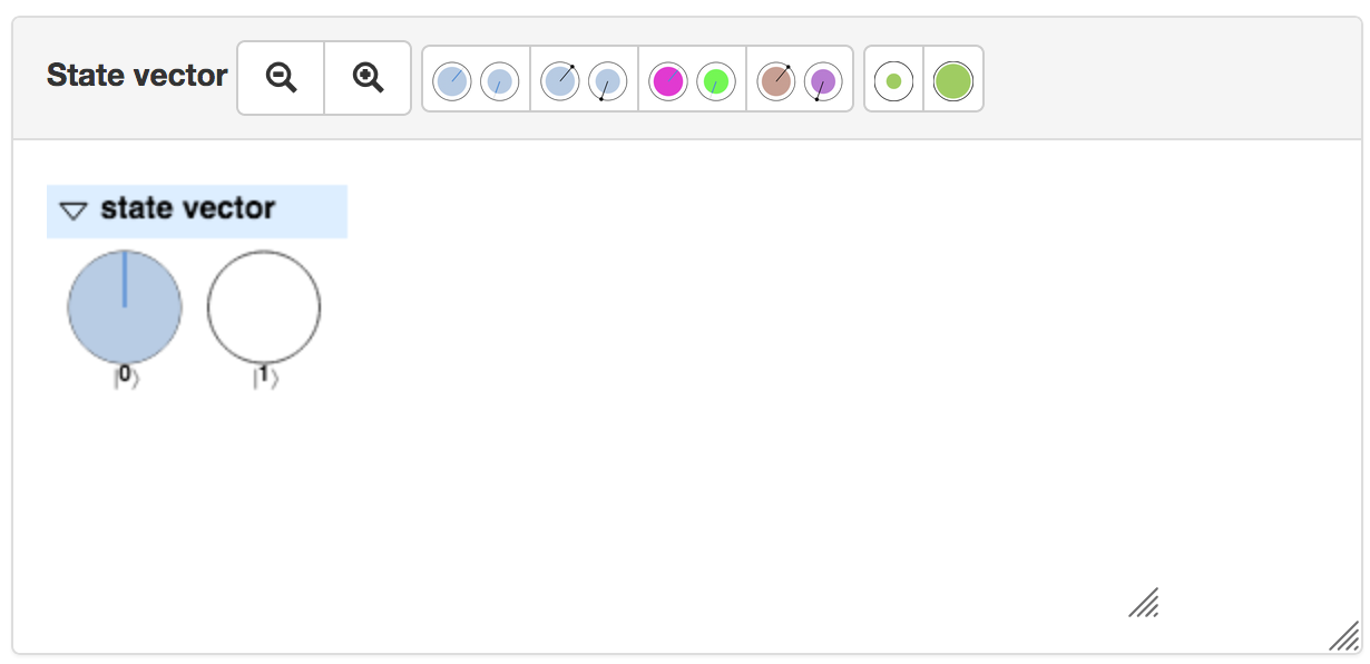
The magnifier buttons can be used to resize the circle notation shown within the circle notation window. Using ctrl-scroll (holding ctrl whilst using a mouse/trackpad scroll gesture) also zooms in/out of the circle notation.
The remaining visualization assistance buttons in the header of the circle notation window provide a number of options for making circle notation more easily visible (especially useful for large QPU registers visualized by large numbers of circles). These include adding ‘rotation needles’ for more prominently showing the rotation of circles, coloring the circles dependent on their rotation, and scaling the filled area of the circles (equivalent to a global phase - see page 20 of Programming Quantum Computers). The filled-area of circles in the circle notation window can also be scaled using shift-scroll (holding shift whilst using a mouse/trackpad scroll gesture).
Note that the point in the circuit at which a QPU’s state is represented in the circle notation window can be altered by interacting with the circuit window (see above).
The output window
The output window displays output printed from a QCEngine program using the qc.print() function. JavaScript output (for example, printed using console.log()) will still appear in your web-browser’s developer JavaScript console as normal.
The magnifier buttons can be used to resize the text-size used in the output window.
The eraser button clears any current output in the output window.
Writing QCEngine code
The QCEngine code written in the code window of the UI is JavaScript. However, a number of JavaScript objects and functions are globally defined in this environment, which expose the QCEngine simulator. Here we cover a quick introduction to these. More detailed information on all available QCEngine objects and functions can be found in the cheatsheet. For a more general (and brief) introduction to JavaScript syntax, see the section on JavaScript.
The most fundamental tool we deal with in QCEngine code is the qc object.
The qc object and single-qubit operations
The qc object represents the whole QPU being simulated by QCEngine, and exposes methods allowing us to associate qubits with this QPU and then manipulate and read them.
We always begin by specifying how many qubits we want to associate with our QPU using the qc.reset() method. For example, we could prepare ourselves for a simulation of an 8-qubit QPU as follows:
// Request 8 qubits for simulation in our QPU
qc.reset(8);
Considered together these 8 qubits can represent any 8-bit number (or, of course, superpositions of such numbers). Before we begin operating on these qubits we can initialize them to be a binary encoding of some integer value using the qc.write() method:
// Write the value 120 to our 8 qubits (01111000)
qc.reset(8);
qc.write(120);
This means we’ve initialized the 8 qubits in our QPU in the states \(|0\rangle|1\rangle|1\rangle|1\rangle|1\rangle|0\rangle|0\rangle|0\rangle\) - the binary representation of 120.
Having a set of initialized qubits, we can consider performing operations on them. The qc object has methods corresponding to many single- and multi-qubit operations. Many of the single-qubit operation methods can be called without any argument to act the same single-qubit operation on all qubits in the QPU separately.
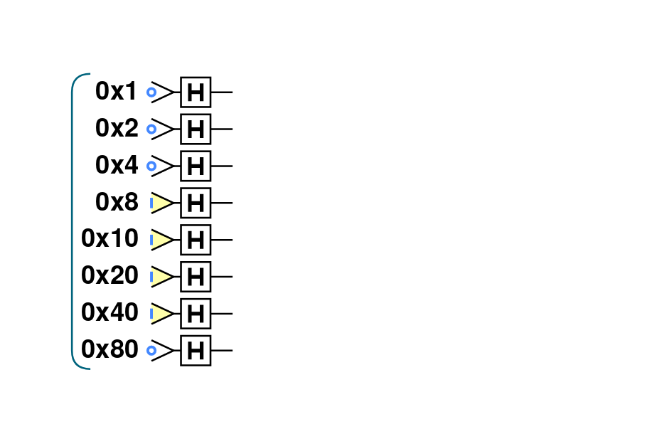
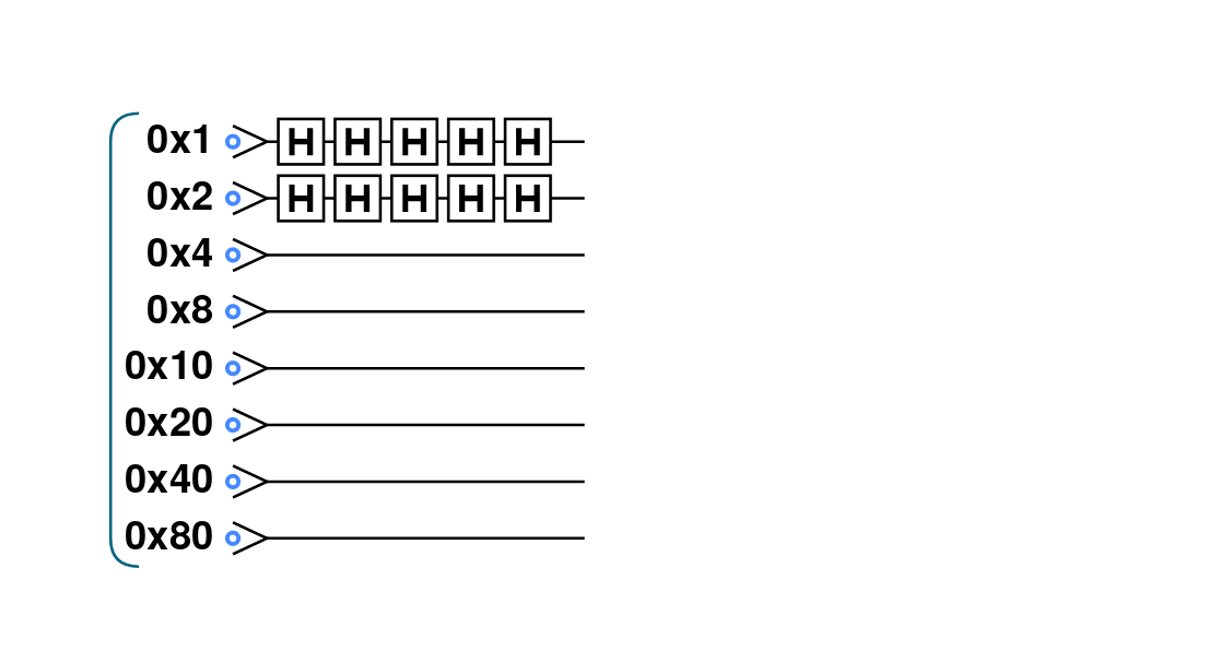
For example, the following code applies a HAD (Hadamard) operation to each qubit in the QPU:
// Perform HAD on all 8 qubits
qc.reset(8);
qc.write(120);
qc.had();
This results in the following circuit:
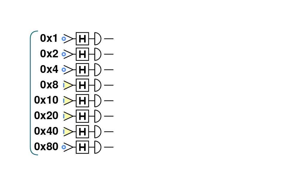
We can similarly READ all 8 qubits in the QPU using the qc.read() method, and again passing no argument to stipulate that the single-qubit READ operation should act on all qubits in the QPU:
// Perform HAD on all 8 qubits
qc.reset(8);
qc.write(120);
qc.had();
qc.read();
Producing the following circuit:
So far we’ve dealt only with single-qubit operations that act on all qubits in the QPU. What if we wanted to act a HAD on only one specific qubit? Or what if we wanted to perform a multi-qubit operation on some specific subset of qubits? To do this we need a method for referencing qubits in the QPU.
Referencing qubits
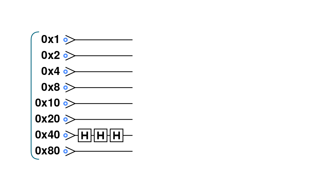
Many of the single qubit methods of the qc object accept a parameter that references the location of a particular qubit to act the operation on. We can reference a qubit using decimal, binary or hexadecimal values. For example, the below snippet shows how each of these methods allows us to act a HAD operation on only the second highest weighted qubit from 8 that we have requested for our QPU:
// Perform HAD only on the second highest weighted of 8 qubits
qc.reset(8);
qc.write(0); // In this case we intialize all qubits to be in |0>
// Each of these have the same effect
qc.had(64); // In decimal - second highest weight qubit correponds to value of 2**6=64
qc.had(0b01000000); // In binary - select out second highest weight qubit
qc.had(0x40); // In hex - 0x80 is 64 in decimal
Note that we employ these addressing methods using JavaScript’s binary and hexadecimal literal syntax (0b and 0x prefixes). As an aside, in each case JavaScript is actually converting the values to decimal before passing them to our method qc.had() (this is why console.log(0b101) will actually print 5).
The above code-snippet corresponds to the following circuit:
We can also easily operate single-qubit operations on a select subset of qubits in a single method call using the JavaScript binary or operator | in our referencing. For example, we can act qc.had() on the first two lowest weight qubits in an 8 qubit QPU as follows:
// Perform HAD only two lowest weighted of 8 qubits
qc.reset(8);
qc.write(0); // In this case we intialize all qubits to be in |0>
// Each of these have the same effect
qc.had(1|2); // In decimal - two lowest weight qubits have values of 2**0=1 and 2**1=2
qc.had(3); // Alternatively specify the single decimal value selecting two lowest weight qubits
qc.had(0b00000011); // In binary
qc.had(0x1|0x2); // In hex
qc.had(0x3); // Alternatively specify the single hexadecimal value selecting two lowest weight qubits
We can see the equivalent effects of these approaches in the circuit diagram produced by this code-snippet:
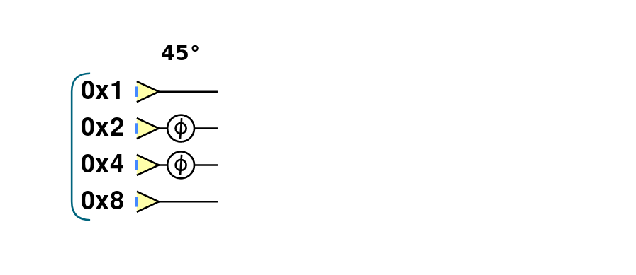
Note that as well as an argument referencing the qubits to act on, some single-qubit operations also take additional parameters. For example, qc.phase() accepts an angle to rotate the relative phase of a qubit through (first argument) as well as a specification of what qubits to act on (second argument). This code performs a relative phase rotation of 45 degrees on the middle two qubits in a 4-qubit QPU:
// Perform PHASE(45) on middle two of 4 qubits
qc.reset(4);
qc.write(0b1111); // In this case we intiialize all qubits to be in |1>
qc.phase(45, 0b0110); // Here we opt to reference our qubits using a binary literal
This produces the following circuit:
Multi-qubit operations
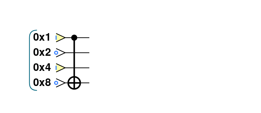
The qc object also has methods for performing multi-qubit operations. These operations normally require a specification of a target qubit, and a control qubit. The target qubit has a certain operation performed on it dependent on the value of the control qubit. For example, qc.cnot() implements the important CNOT operation, and takes a reference to the target qubit as its first argument, and a reference to the control qubit as its second argument:
// Perform CNOT between highest (target) and lowest (control) weighted of 4 qubits
qc.reset(4);
qc.write(5);
qc.cnot(0b1000, 0b0001); // Here we opt to reference our qubits using binary literals
Which results in the following circuit:
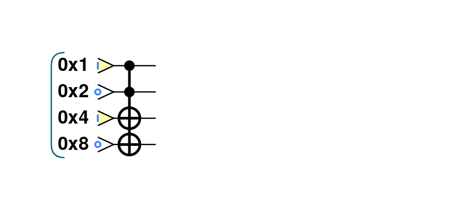
We can easily specify more target or control qubits for a multi-qubit operation, using the referencing system we introduced above. For example, consider the following code-snippet employing a CNOT with two target and two control qubits and its associated circuit:
// Perform CNOT between two highest (targets) and two lowest (controls) weighted of 4 qubits
qc.reset(4);
qc.write(5);
qc.cnot(0b1100, 0b0011); // Here we opt to reference our qubits using binary literals
Grouping qubits using qint
Sometimes we may wish to logically associate small subsets of a full QPU’s set of qubits. We can think of such smaller groupings as ‘registers’ within our QPU. This kind of association can be achieved using qint objects. After a set of qubits have been requested for a QPU using the qc.reset() method, we can draw qubits from this available collection to associate with a qint using the qint.new() method. For example, the below code-snippet defines one 2-qubit qint and one 6-qubit qint from a QPU of 8 qubits.
// Define two qints
qc.reset(8);
qc.write(0); // Initialize all qubits at once before introducing qints
var myqint1 = qint.new(2, 'My Qint 1');
var myqint2 = qint.new(6, 'My Qint 2');
We can see that the qint object is created with two arguments. The first specifies a number of qubits to associate with the qint. Note that this number of qubits is drawn from the stack available in the QPU, starting from the lowest weight first. We can see this in the circuit diagram generated by this code-snippet:
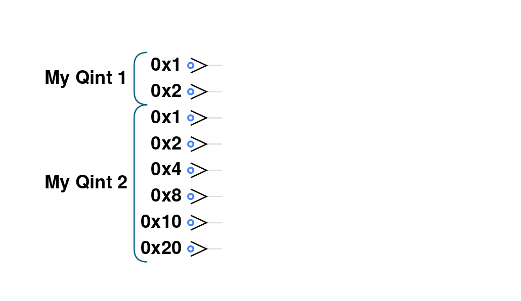
This circuit diagram also shows that the second argument to the qint object is a label, which is shown on circuit diagrams in the circuit window to help us identify different qint’s that we have defined. You’ll notice that we’ve also assigned our new qint objects to JavaScript variables. This is crucial, as these new objects implement many single- and multi-qubit methods, allowing us to act on qubits in reference to these smaller qint collections.
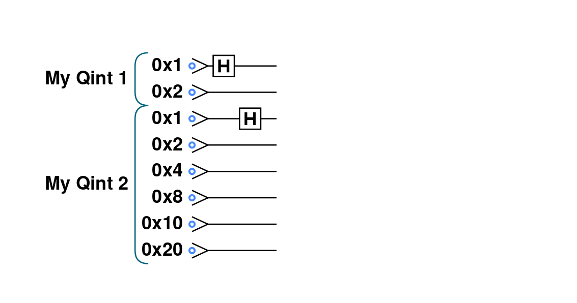
For example we can act a HAD operation on the lowest weight qubit in each qint as follows:
// Define two qints
qc.reset(8);
qc.write(0); // Initialize all qubits at once before introducing qints
var myqint1 = qint.new(2, 'My Qint 1');
var myqint2 = qint.new(6, 'My Qint 2');

// Act HADS on highest weight qubit in each qint.
// Note that our references are now interpreted in relation
// to the qint, not the whole QPU as they were with the qc object
myqint1.had(1);
myqint2.had(1);
Giving the following circuit:
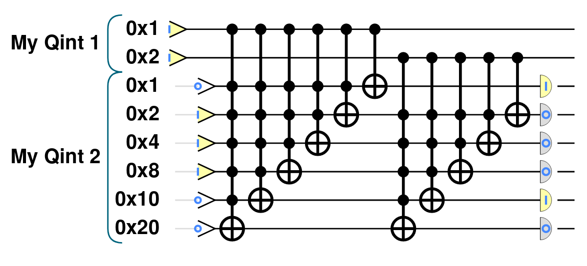
qint objects are especially useful because they allow us (as their name suggests), to allocate a set of qubits to represent an integer (or other datatype), which we can then use in arithmetic, like we would in conventional CPU code. For example, the qint object implements a qint.add() method, which takes another qint object as an argument, and produces the circuit required to perform quantum addition (i.e. addition that respects superpositions of values) between the integer values encoded in the two qint objects:
// Define two qints
qc.reset(8);
// Define two qints
var myqint1 = qint.new(2, 'My Qint 1');
var myqint2 = qint.new(6, 'My Qint 2');
// Write a value of 3 to the first qint
myqint1.write(3);
// Write a value of 14 to the second qint
myqint2.write(14);

// Perform (quantum) addition between the values stored in the two qints
// Note will add onto the myqint2 register
myqint2.add(myqint1);

// Read output
myqint2.read() // Gives answer 17